Output Display (OUT)
The output display can load the contents of the databus and display it as a decimal integer on the 4x 7-segment displays.
It supports the display of either a unsigned \(\left[ 0, 255\right]\) or 2s-complement signed \(\left[ -128, 127\right]\) 8-bit value.
Mode of Operation
The value to display is read from the databus and saved in a SN74LS273 octal d-type flip-flop on a riding clock edge when the \(LOAD\) signal is active. Due to the lack of an enable pin on the register IC, the load signal is implemented by ANDing the \(CLK\) and \(LOAD\) signal.
BCD decoder
The decoding of the binary display is implemented as a lookup table (LUT) using a 28C16 2K x 8-bit parallel EEPROM. This IC has 11 address pins \(A_0-A_{10}\) of which the first 8 are used to input the display-value. The next 2 address bits are used to select the digit of the display currently active. This leaves the last address pin to select the display mode (unsigned or signed) using \(\mathrm{OUT\colon S_3}\).
Digit multiplexing
Since the EEPROM decoder can only drive a single digit at any time with it’s 8 output lines, the 4 digits need to be multiplexed. This is done by sequentially driving the common-cathode pin of each digit low while simultaneously setting the \(A_8\) and \(A_9\) address pins of the EEPROM which in turn will drive the anodes of the selected display digit to the apropriate value.
The binary digit select signal that drives the address lines is implemented by a single SN74LS76 dual J-K flip flop IC to implement a 2 bit binary counter. This counter is driven by an astable LM555 oscillator that runs fast enough to cycle through the digits without perceivable flickering:
The bianry coded digit select signal is then decoded using a SN74LS139 2-line to 4-line decoder with active low outputs to drive the cathodes.
LED Output Drive
According to the datasheet of the decoder EEPROM, the chip can drive \(10-20mA\) with a \(0.5 - 1.5V\) drop in its output voltage. This may be too big of a drop when combined with the \(220Ω\) series resistors when used for higher voltage drop LED displays (like blue or white). If you have trouble with the output display being too dim or not lighting up at all, replace the resistor networks \(\mathrm{RN}_1\) and \(\mathrm{RN}_2\) with jumpers or choose a lower resistance network.
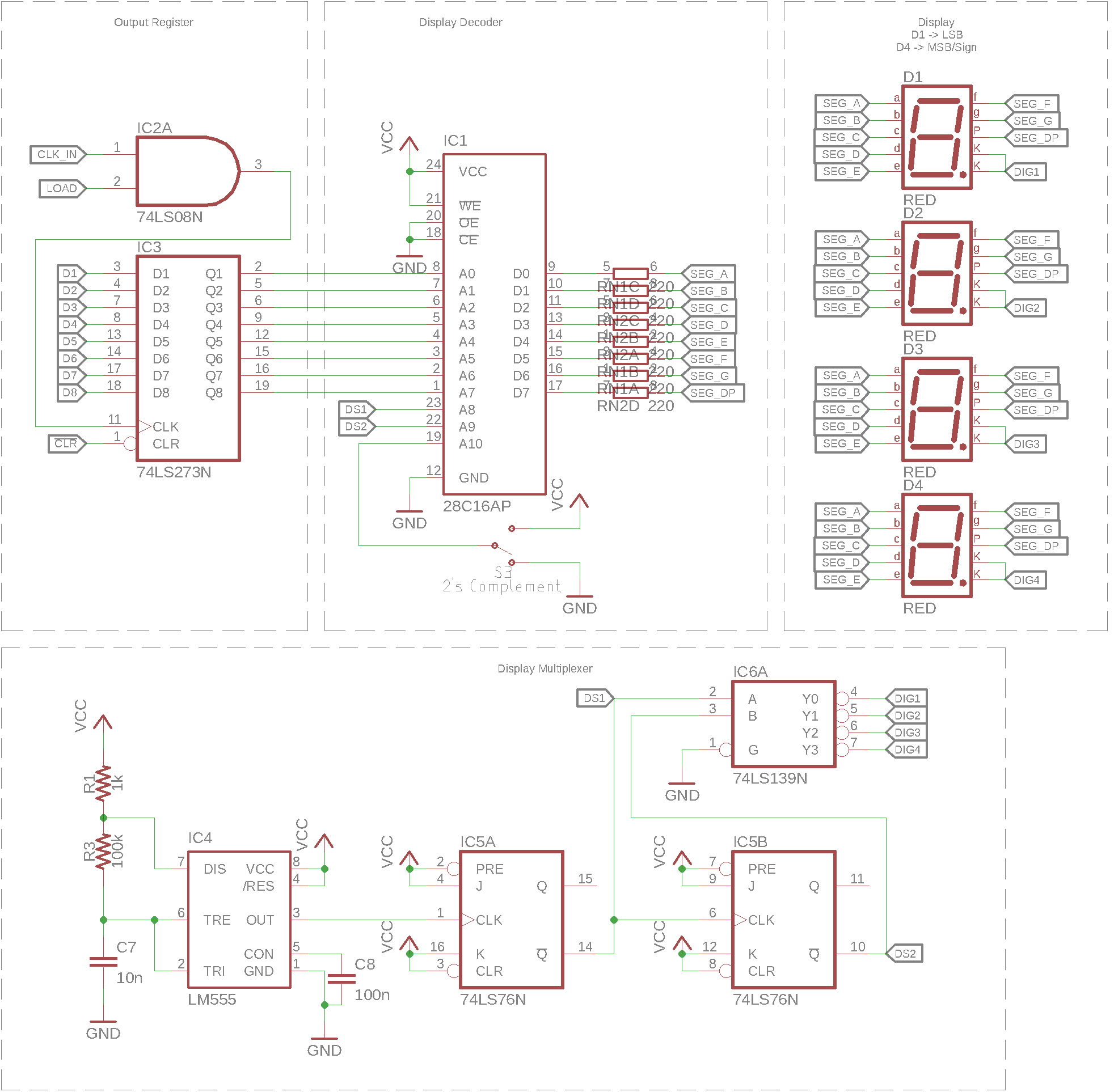
Schematic