Clock (CLK)
The clock module is responsible for all time related coordination between the seperate modules.
Mode of Operation
The module has 2 outputs that feed into the other modules, the positive clock line (\(CLK\)) and its logical inverse (\(\overline{CLK}\)). The \(\overline{CLK}\) signal is always low when the clock signal is high and vice-versa, this way the processor has 2 clock signals that are on a 180° phase difference.
The source for the clock pulses is selectable via the Source Select switch and can either be set to run mode or single-step.
Run mode
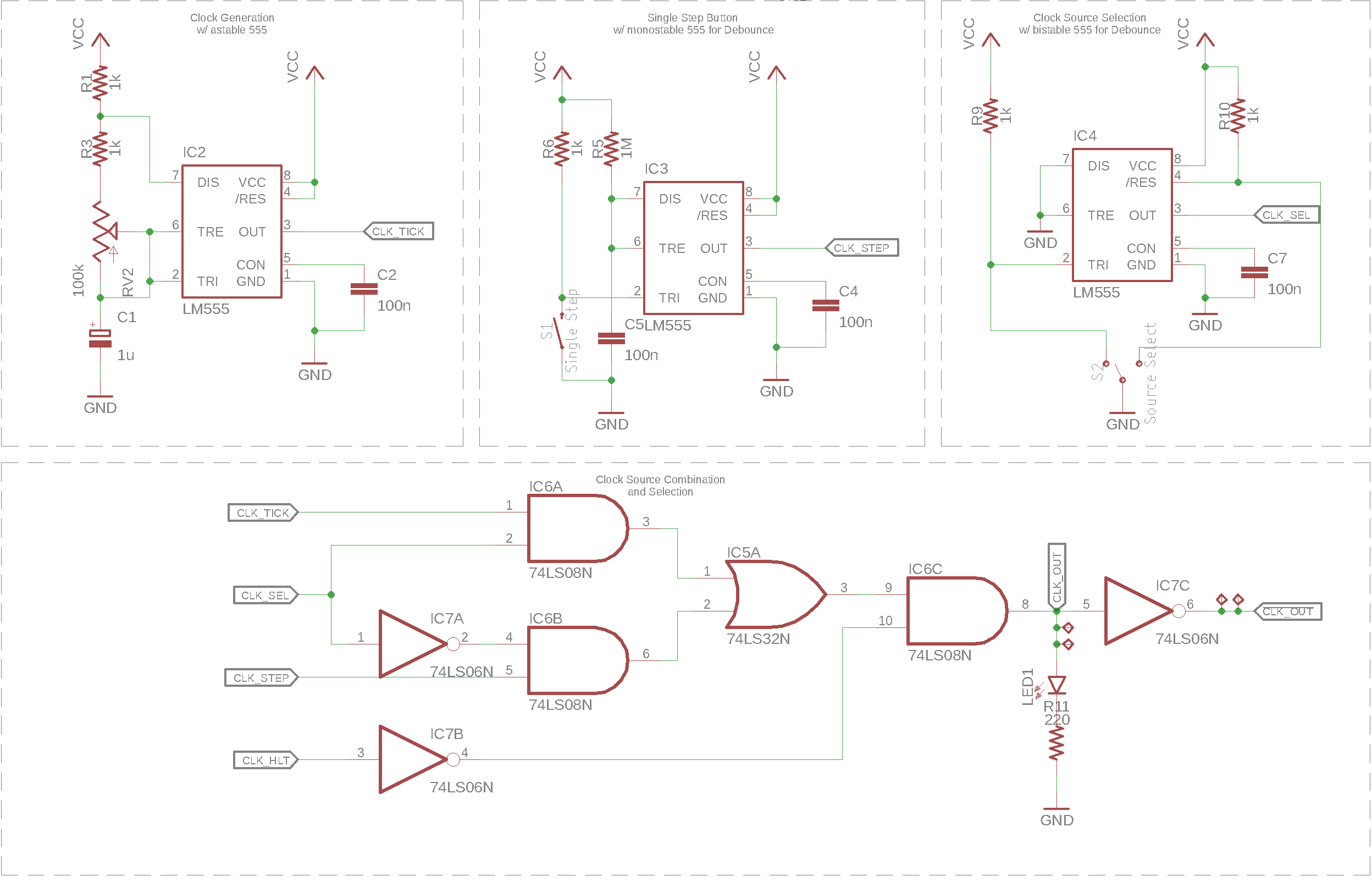
In run mode, the clock signal is created by a 555 timer in astable configuration. The dutycycle of the signal is 50%, while the frequency can be set using a potentiometer. The clock frequency is set by \(\mathrm{CLK\colon R_1}\), \(\mathrm{CLK\colon R_2} + \mathrm{CLK\colon RV_2}\) and \(\mathrm{CLK\colon C_1}\):
Single-step mode
In single-step mode, the positive clock signal is set by pressing the Single Step button and cleared after releasing it. Another 555 timer in monostable configuration is used to debounce the button presses to avoid accidentaly creating multiple steps on a single press. The debounce time is set by the RC network consisting of \(\mathrm{CLK\colon R_6}\) and \(\mathrm{CLK\colon C_5}\) and can be calculated as:
Clock Source selection & Halt signal
The actual output signal is a logical combination of the two 555 timer outputs and the output of a third 555 in bistable mode. This third 555 is used to debounce the signal of a single-pole double-throw (SPDT) slide-switch. The debouncing is neccessary because otherwise a switch bounce could generate multiple clock ticks when switching modes while the 2 clock signals have a different state.
In any way, a clock pulse is only output if the halt signal (\(CLK_{HLT}\)) is inactive. This halt signal is part of the control word (CW) and can be used to stop program execution.
Schematic