Instruction Decoder (ID)
The instruction decoders job is to generate the control word (CW) which consists of the control lines of the other modules thus controlling the behaviour of the processor and all its submodules. The control word is created based on the current instruction, the microinstruction in this instruction and the state of the processors flags.
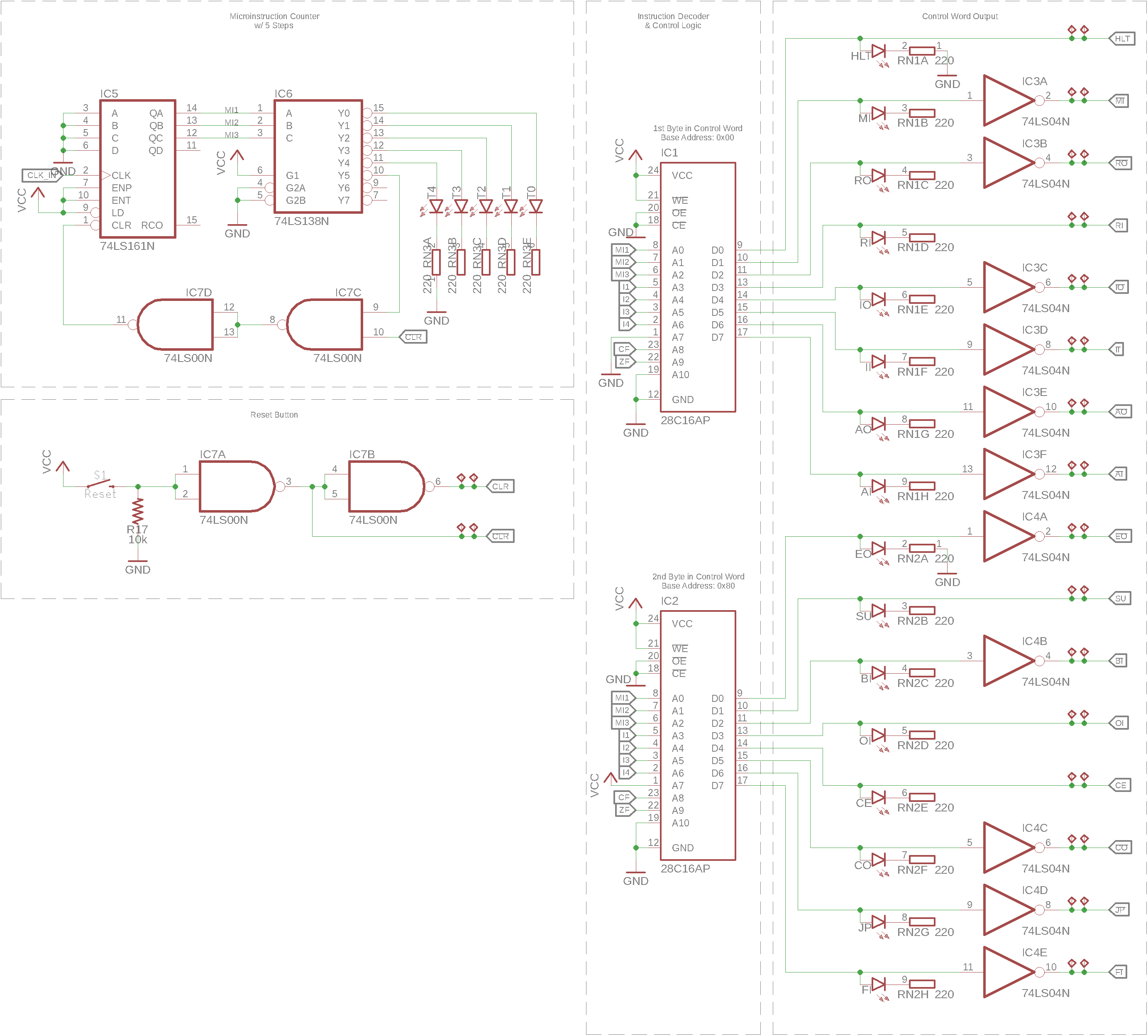
Mode of Operation
The instrcution decoder uses 2 28C16 2K x 8-bit parallel EEPROMs to decode the combination of the 4 instruction bits \(\mathrm{I_1} - \mathrm{I_4}\), the micro instruction counter \(\mathrm{MI_1} - \mathrm{MI_3}\) and the flags \(\mathrm{CF}\) and \(\mathrm{ZF}\) to a 16-bit control word. The address line \(\mathrm{A_7}\) is pulled low for \(\mathrm{IC_1}\) while tied to VCC for \(\mathrm{IC_2}\). This way it is possible to flash both EEPROMs with the same lookup table for instruction decoding.
CW Lookup Table
The control word for each microinstruction for all instructions is described in the instruction set architecture.
Microinstruction Counter
The current microinstruction step is counted by a SN74LS161 4-bit syncronous counter of which only 3 bits are used to count the 5 possible number of microsteps. The outputs \(\mathrm{Q_A} - \mathrm{Q_C}\) of the counter are decoded using a SN74LS138 3-line to 8-line decoder. The output of the 6th decoded line is fed through a dual NAND gate to form an OR gate with inverted inputs. Thus the counter will be reset to zero, immediately after reaching the value 6, effectivley counting 0-5. The second input to the first NOR gate implements a active-low reset signal for the counter connected to the reset circuit.
Active High Control Word
Some lines in the CW are active-low. To normalize the behaviour of all control lines, to active high, the 2 inverters \(\mathrm{ID\colon IC_3}\) and \(\mathrm{ID\colon IC_4}\) are used to flip the polarity of the active low signals before outputting. This makes programming of the instruction decoder easier.
System Reset
The control word module also contains the reset circuit which controls the \(\mathrm{CLR}\) signal and it’s logical inverse \(\overline{\mathrm{CLR}}\) that is used for modules with an active-low clear line.
To buffer the signal of the reset button and invert it’s state, the 2 remaining NAND gates of the microinstruction counter are used.
Schematic