Arithmetic Logic Unit (ALU)
The ALU enables the Processor to perform simple arithmetic operations. In fact, it only can perform the addition or substraction of the values in the two data registers RA and RB:
Mode of Operation
Addition
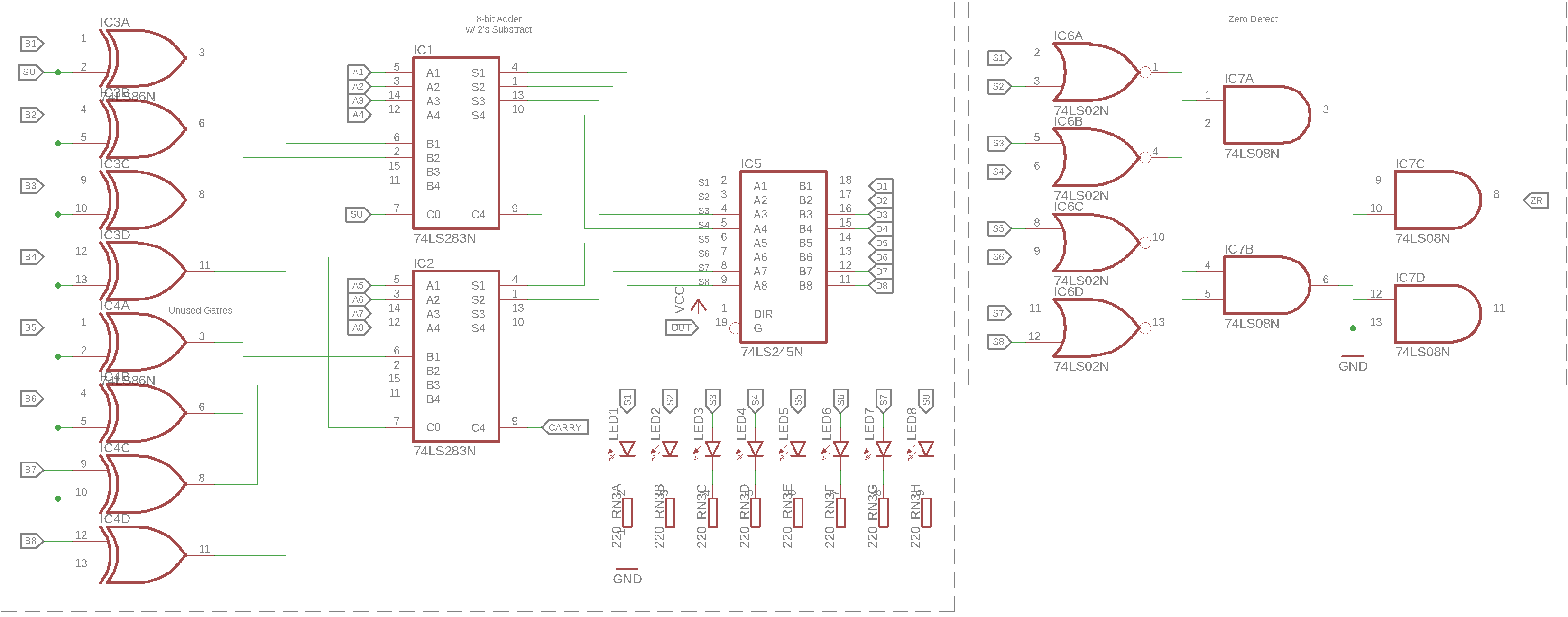
The ALU uses 2 74LS283 4-bit binary adders with carry. The carry output (\(\mathrm{ALU\colon C_4}\)) of \(\mathrm{ALU\colon IC_1}\) is connected to the carry input (\(\mathrm{ALU\colon C_0}\)) of \(\mathrm{ALU\colon IC_2}\), thus a carry after bit 4 is propagated to the second nibble of the result. The inputs A and B of the ICs are connected directly to the outputs of the 74LS173 registers of RA and (through XOR gates) RB instead of the DB. For addition, the substract line \(\mathrm{SU}\) line is low, thus the XOR gates output the same value as the input from RB. To only drive the DB lines when the result of the computation is needed, another 74LS245 is used as tristate buffer, enabling the display of the result on \(\mathrm{ALU\colon LED_{1-8}}\) without driving the DB.
Substraction
For substraction of RA and RB, the \(\mathrm{SU}\) signal is active, thus the output of the XOR gates is always the logical inverse of the input from RB. Thus the second byte into the 8-bit adder is the 1s complement of RB. To calculate a 2s complement result however, the \(\mathrm{SU}\) signal also drives the \(\mathrm{ALU\colon C_0}\) input of \(\mathrm{ALU\colon IC_1}\), effectivley adding 1 to the result.
Flags
The carry signal \(\mathrm{CY}\) can be read directly from the \(\mathrm{ALU\colon C_4}\) pin of the second nibble adder \(\mathrm{ALU\colon IC_2}\).
For the zero flag signal \(\mathrm{ZR}\), all output bits are NORed together. Since there are no 8-input NOR gates available (at least in the commonly available 74LS series logic family), a quad 2-input NOR gate (74LS02) is used to NOR every 2 bits together, then each of the outputs is ANDed together using a quad 2-input AND gate (74LS02) until only a single signal is left that will be active high when all ALU output bits are cleared.
Schematic